Checking CAD Models for Thermoformability: The Designer's Guide
Whether a plastic part is thermoformable is determined in the CAD model. Anyone who discusses geometry, wall thicknesses, and demoldability only after the first sampling pays for this loop with tool modifications, material waste, and lost weeks in the project timeline. This can be avoided during design: with a structured check that evaluates each model along this guide and makes typical sources of error visible early on.
Sarah Guaglianone
Updated on July 2, 2026
Share
Contents
How to Check Your CAD Model for Thermoformability - The Essentials
Checking a CAD model for thermoformability means evaluating the component along a defined pull direction on seven points: 3D model quality, pull direction and tool side, draft angles, radii, draw ratio and resulting wall thicknesses, narrow spots and undercuts, as well as documented approval.
The check can be performed manually with the standard functions of common CAD systems such as CATIA, Creo, NX, SolidWorks, or Inventor.
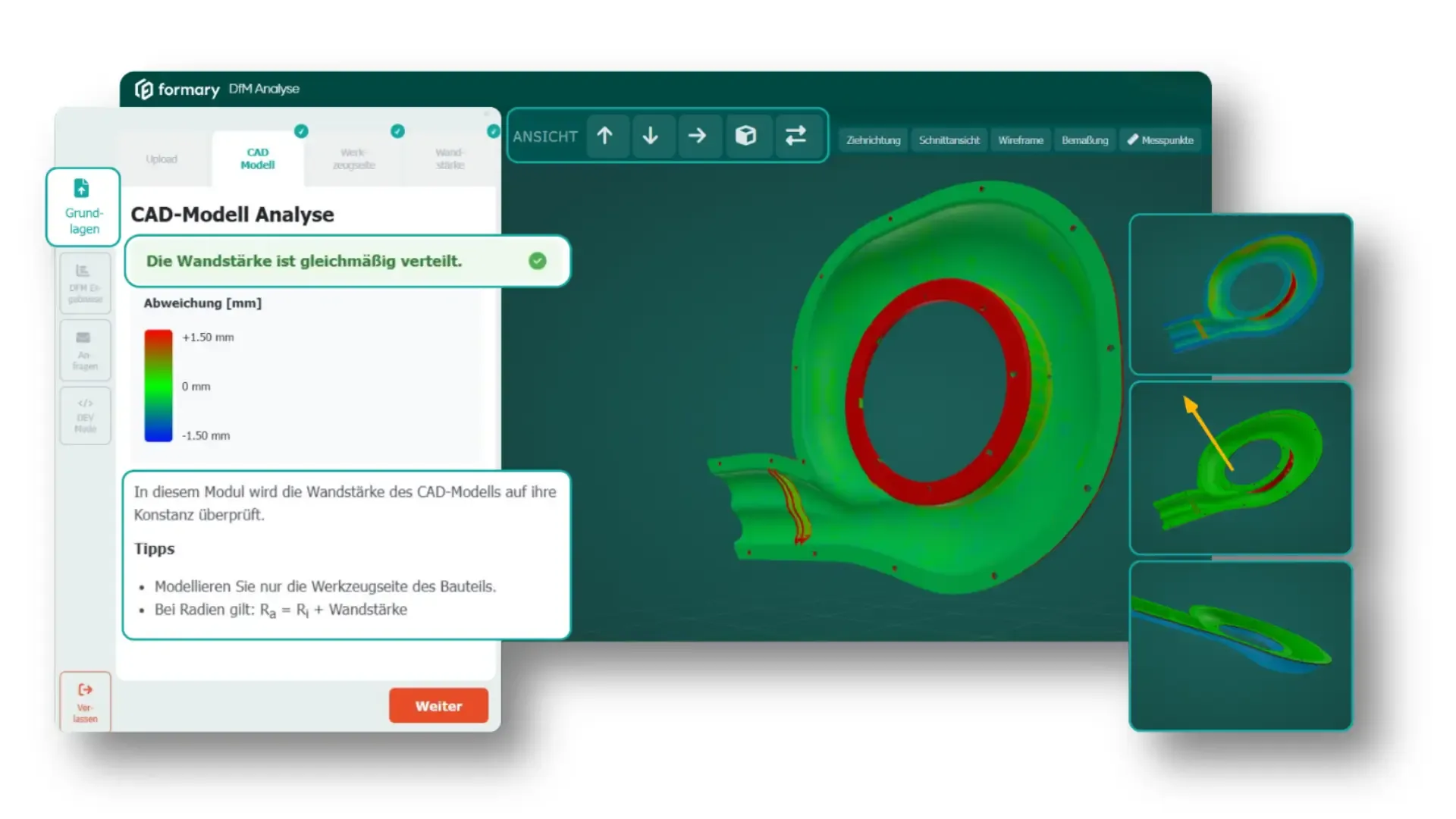
The formary DfM analysis performs this check automatically on a STEP upload and delivers a color-coded 3D evaluation and a PDF report.
→ Do you have a CAD model you'd like to check for thermoformability? Book a demo and we'll review your data together in our DfM analysis.
Why a Thermoformability Check in CAD is Worthwhile
In plastic thermoforming, a heated semi-finished sheet or film is drawn over a tool and brought into shape by vacuum or compressed air. The component is therefore not created by injecting material into a closed cavity (as in injection molding), but by stretching an originally uniform-thickness starting material over a mold. This creates wall thicknesses, radii, and geometric transitions directly from the subsequent material distribution.
Why the Tool Side is Decisive
For design, this has two important consequences. First, thermoforming is typically a single-sided tool-bound process. The forming contour is on one tool side. Subsequently, the component must be safely demolded from the tool. Geometries with undercuts, closed contours, or missing draft angles are therefore critical or not thermoformable. Even in the CAD model, it should therefore be clearly defined which side is the tool side and in which direction the component is demolded.
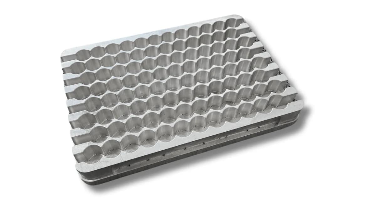
Example of a thermoforming tool made out of aluminium
Why Wall Thicknesses Cannot Be Built Up Freely
Second, local material accumulations cannot be built up arbitrarily. While in injection molding, ribs, domes, or massive functional areas can be specifically formed with additional material, a thermoformed part is created solely by forming and stretching the existing sheet or film.
Extreme material thickenings or highly material-intensive features are therefore only possible to a limited extent or not at all. The decisive factor is not only the drawn geometry, but also the question of how much the material thins out in deep, narrow, or sharp-edged areas.
Not Every CAD Geometry is Thermoformable
Not every geometry suitable for injection molding, 3D printing, or machining can automatically be thermoformed. This is precisely where Design for Manufacturing comes in: The CAD model is checked early to see whether pull direction, tool side, wall thickness progression, radii, demoldability, and critical geometries match the thermoforming process.
The earlier this check takes place, the easier design adjustments can still be implemented. Especially in the development phase, small changes to radii, drafts, or component depths can later have major impacts on tooling costs, sample quality, and project duration.
Typical Consequences of Late Feasibility Checks
When a CAD model is only evaluated for thermoformability after the first sampling, critical areas often become visible late. Typical consequences are:
wall areas that are too thin
torn corners
components that cannot be safely demolded from the tool
subsequent tool modifications
additional coordination loops before approval or series start
A design-accompanying check reduces these risks because critical geometries are identified before tooling, inquiry, or sampling.
How to Perform the Check
The following guide can be applied directly to a current STEP model: either manually with the standard functions of your CAD system or automatically via the formary DfM analysis.
This makes the most important influencing factors visible: pull direction, tool side, demoldability, radii, draw ratio, resulting wall thicknesses, and possible undercuts or narrow spots.
7 Points to Consider When Performing a Feasibility Check on Plastic Thermoformed Parts
The following seven check points help to systematically evaluate a CAD model for its thermoformability. They show which aspects designers and developers can already check before the inquiry and at which points an automated thermoforming check creates additional security.
1. CAD Model Hygiene and Geometry Validity
Before you check the content, analyze the model quality. Because a thermoformability check is only as reliable as the CAD model on which it is based. It is particularly important that the model realistically depicts the thermoformed component and does not contain unnecessary assembly information.
Therefore, first check:
Closed solid body: The model should be built as a clean solid body and contain no open surfaces.
Constant wall thickness in the CAD model: The component should be modeled with a uniform initial wall thickness. Ideally, a surface is first modeled and then thickened. This is the most reliable way to ensure constant wall thickness in the CAD model.
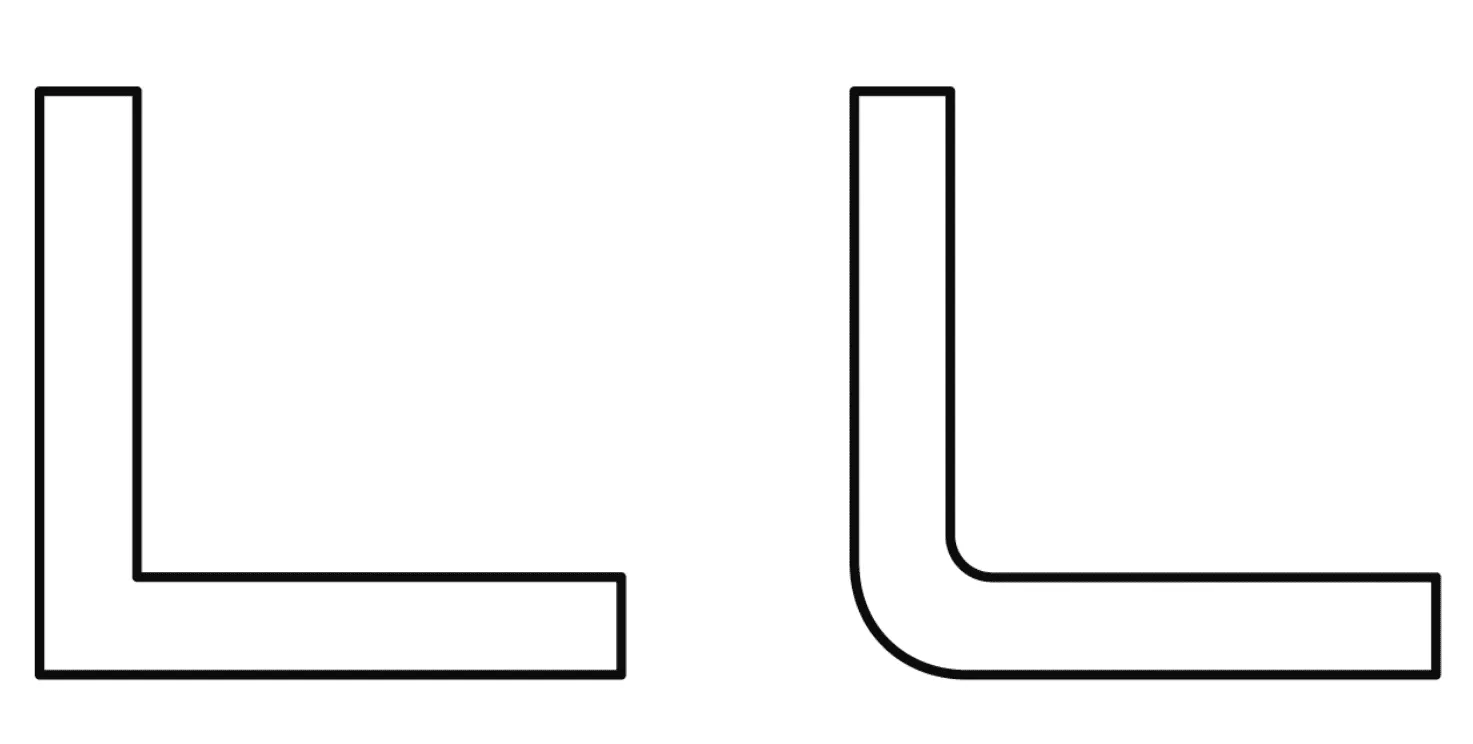
Radii at all relevant geometric transitions: Apart from later cutting or trimming edges, radii should be provided on the model. Sharp inner and outer corners often lead to local thinning, cracking, or uneven material flow during thermoforming.
Format: Export as STEP (.step / .stp). STEP is the most robust neutral exchange standard for thermoforming evaluations and the input data type that the formary thermoforming check processes.
Clean zero point: A sensibly set zero point, ideally in the center of the component, facilitates further processing and evaluation of the model.
Simplification: Hide screws, inserts, logos as separate components. What is being checked is the thermoformed shell, not the assembly.
Most CAD systems offer geometry diagnostics with which open surfaces, self-intersections, and faulty normals can be found before export. Run this check once before you pass on the model.
💡 Important: A constant wall thickness in the CAD model does not mean that the subsequent thermoformed part has the same wall thickness everywhere. It only represents the defined initial geometry. The actual wall thickness distribution only occurs through material stretching in the thermoforming process.
2. Define Pull Direction and Tool Side
Thermoforming knows only one pull direction. This does not necessarily have to be already defined by the orientation of the CAD model, but should be defined before the actual thermoformability check. Only then can radii, draft angles, undercuts, and wall thickness progressions be meaningfully evaluated.
In practice, this means:
Which axis is the subsequent demolding direction?
Which side is directly against the tool?
Which side must be manufactured dimensionally accurate?
Which contour is functionally decisive: inner contour or outer contour?
Only with a defined pull direction and specified tool side can all further checks be meaningfully evaluated.
Why the Dimensionally Accurate Side is Important
The choice of forming method determines which side of the thermoformed part lies directly against the tool and can therefore be reproduced more accurately.
This side is particularly important when certain areas later fulfill a functional task, for example form nests in a tray or contact surfaces in an inlay. It should therefore already be clear in the CAD model which side must later be manufactured particularly accurately.
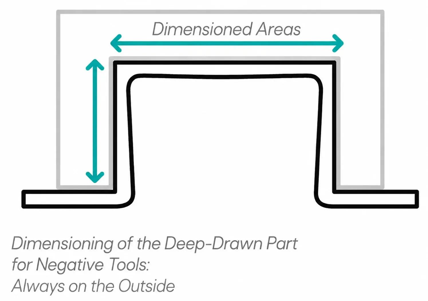
Negative Molds: Outer Contour Dimensionally Accurate
In a negative mold, the heated material is drawn into a cavity. The material is pressed against the tool-facing outside. As a result, the outer contour is particularly dimensionally accurate.
The inner contour, on the other hand, results from material thickness, draw ratio, and material flow. It is therefore only dimensionable to a limited extent. Negative molds are particularly suitable when the outer component geometry is decisive or when depressions, pockets, and cavities are to be depicted.
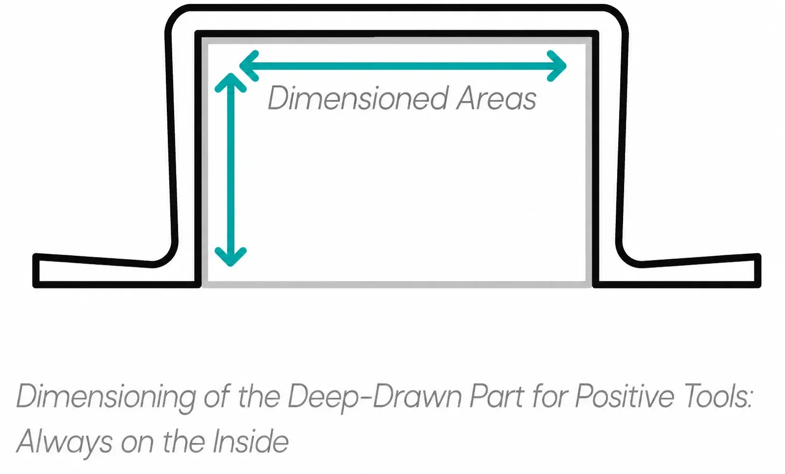
Positive Molds: Inner Contour Dimensionally Accurate
In a positive mold, the material is drawn over a raised tool contour. The material rests on the tool-facing inside. As a result, the inner contour can be dimensioned precisely. The outer contour results from material thickness, stretching, and flow behavior. Positive molds are particularly suitable when inner contours are functionally decisive, for example in trays, inlays, or workpiece carriers in which components must be safely guided, fixed, or positioned.
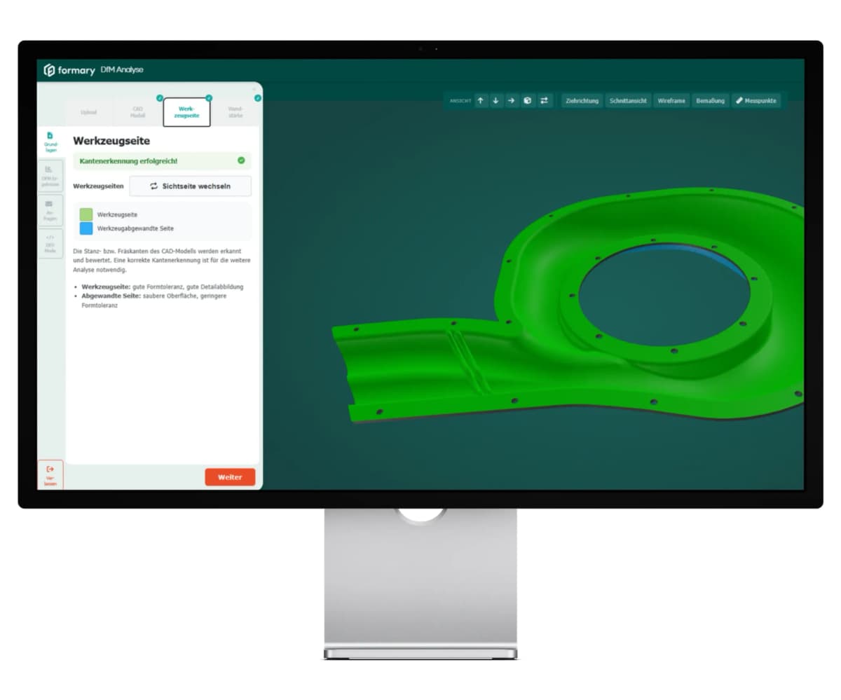
What This Means for CAD Checking
For design, this means: Before the thermoformability check, determine which side of the component will later be decisive. For trays, inlays, or workpiece carriers, the inner contours of the nests are often relevant because components must be securely fixed there. For housings, covers, or cladding parts, on the other hand, the outer contour may be decisive, for example because of installation space, optics, or adjacent assemblies.
Only when pull direction, tool side, and dimensionally accurate side are defined can draft angles, radii, undercuts, and wall thickness progressions be meaningfully evaluated.
💡 Note: In the formary thermoforming check, punching or milling edges in the CAD model are automatically recognized.
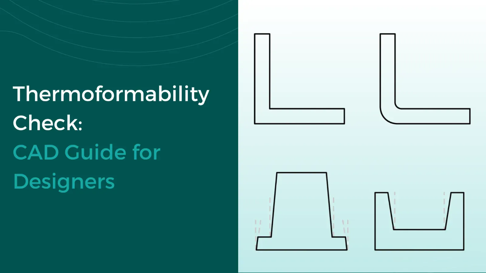
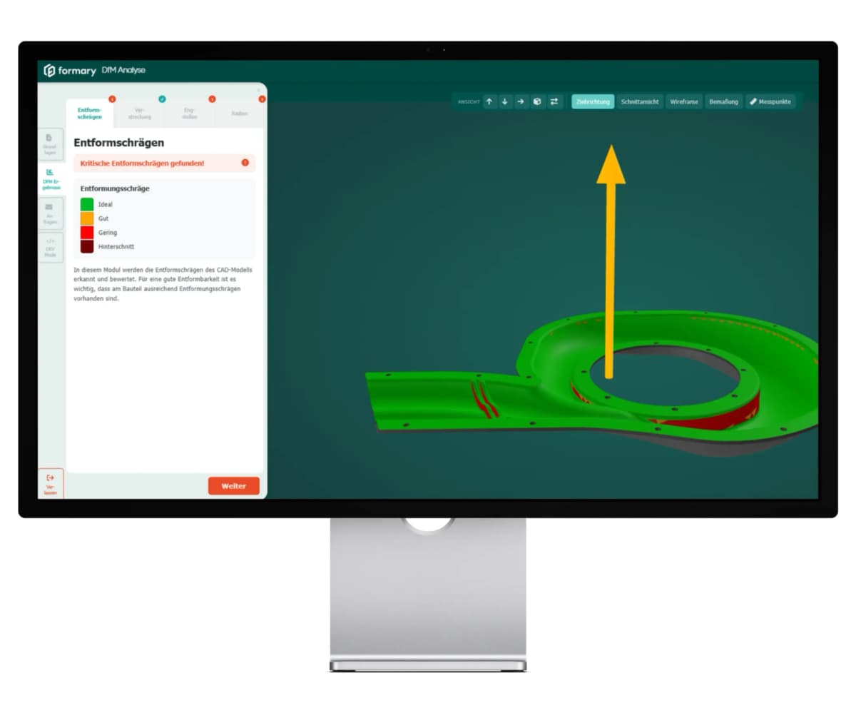
3. Check Draft Angles
Every surface parallel to the pull direction needs a draft angle, otherwise the component will jam in the tool. A rule of thumb in thermoforming is to demold inner surfaces more generously than outer surfaces, because the shrinking material would otherwise remain against the tool.
Most CAD systems offer a draft or draft analysis in which you specify the pull direction as the Z-axis and the software colors all surfaces below a defined limit angle red. Pay particular attention to walls perpendicular to the Z-axis on stiffening ribs, deep cavities, and webs.
💡 Note: The formary thermoforming check performs this step automatically; critical areas without sufficient draft are highlighted.
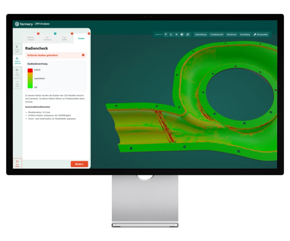
4. Analyze Radii
Radii that are too small are the most common reason a component tears or thins extremely locally. The thermoforming process distributes the material over curvatures; sharp corners force the material into an area where it can no longer flow.
Check systematically:
Outer radii at transitions from floor to side wall.
Inner radii on webs, stiffeners, and depressions.
Corner radii where three surfaces meet are the most critical spots.
Use the curvature or radius analysis of your CAD system to mark radii below your defined limit value in color.
💡 Note: In the formary DfM analysis, radii that are too small are automatically detected and highlighted in color.
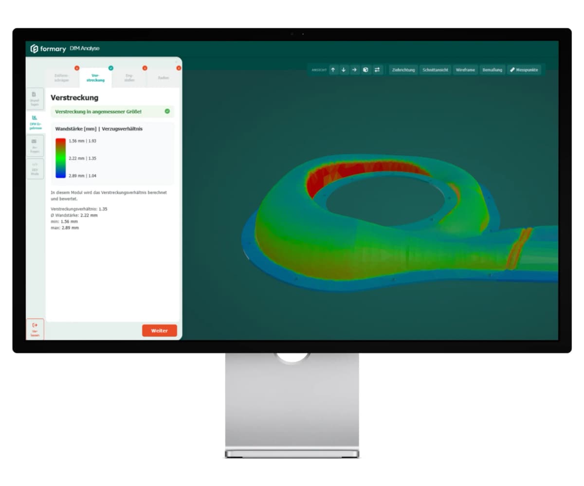
5. Draw Ratio and Resulting Wall Thickness
This is the actual crux that distinguishes thermoforming from other processes. From a semi-finished sheet of defined thickness, a component is created whose local wall thickness depends on the draw ratio: the deeper the geometry at a location, the more the material thins out.
Important: A constant wall thickness is usually not possible with thermoforming. The material is stretched from an originally approximately uniform-thickness roll or sheet stock. The resulting wall thickness distribution is therefore not constant after forming, but depends on how much the material is stretched in the individual areas of the component.
These thickness differences can be reduced through design adjustments and process engineering measures, for example through larger radii, lower component depths, adjusted pull direction, or pre-stretching with an upper punch. However, they cannot be completely avoided. The exact subsequent wall thickness also remains process-dependent and can only be approximately assessed before production.
Practical checking:
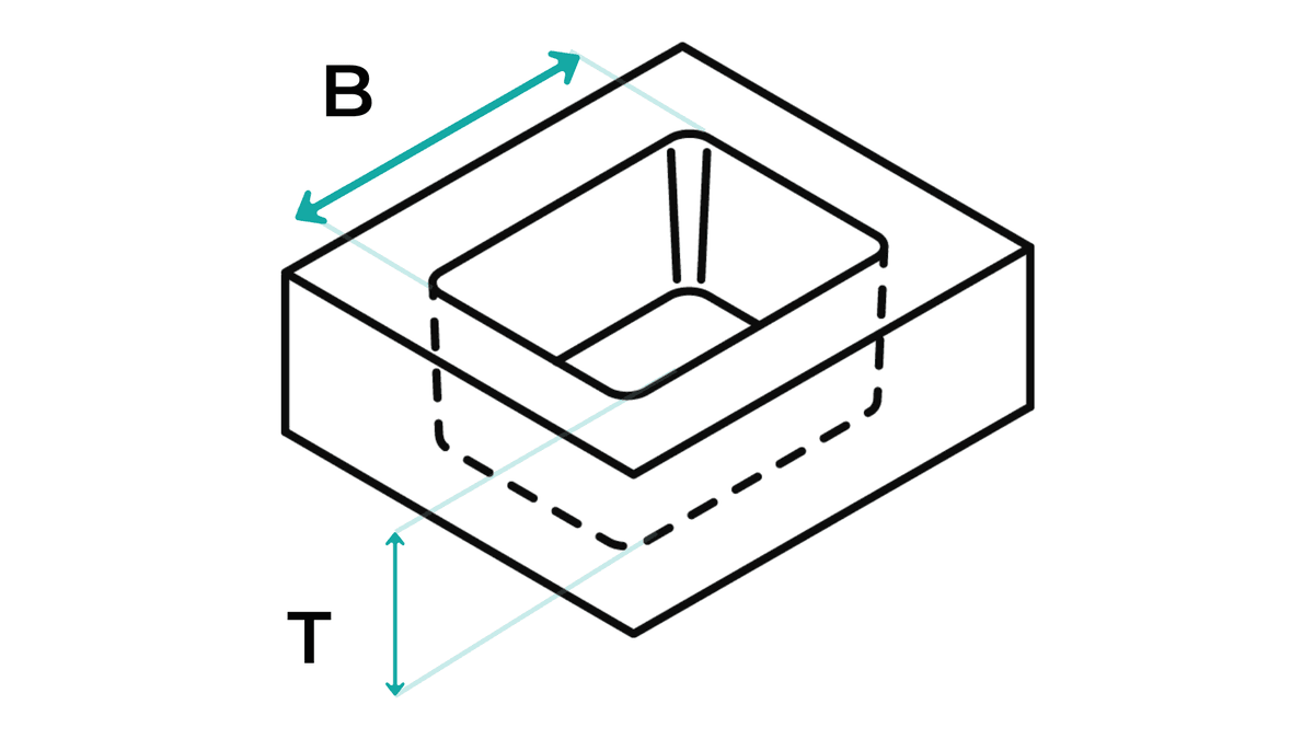
Depth-to-width ratio of the deepest cavity. The larger, the stronger the local thinning.
Local peaks at sharp corners or narrow webs where the material is disproportionately stretched.
Minimum wall thickness at the thinnest point, compared with your mechanical requirement.
Functional wall thickness requirements: Which areas must achieve a minimum wall thickness for mechanical, optical, or assembly-related reasons?
💡 Note: In classic CAD systems, this can only be derived through manual sections and estimates. The formary thermoforming check calculates this automatically and computes the local draw ratio and makes visible how much the material is stretched in different areas of the component.
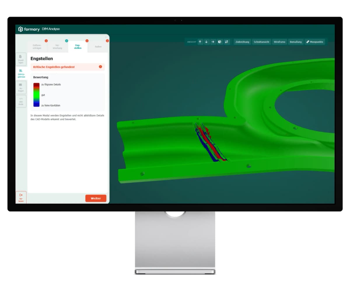
6. Narrow Spots, Edges, and Undercuts
Here you identify geometries that are theoretically drawable but practically not thermoformable:
Illustration of an undercut
Narrow spots: narrow slots, filigree depressions, or cavities into which the warm material does not flow.
Undercuts against the pull direction: Areas that the tool cannot release. If essential, slides or multi-part tools must be planned, with corresponding cost and complexity surcharges.
Punching and cutting edges: from which edge the semi-finished product is later trimmed. These edges influence the tool contour and the usable component height.
Visualize this in CAD via sections along the pull direction.
💡 In the automated check, filigree areas with insufficient wall thickness are displayed in red; fine cavities that cannot be depicted by the material are shown in blue.
7. Evaluation and Documentation
A CAD check is only useful if the result flows documented into the next iteration. Record for each geometry area:
Status (okay, critical, not thermoformable).
Specific change recommendation (enlarge radius, increase draft, reduce depth).
Responsible person and iteration loop.
Next Step
If you prepare your CAD model based on these seven points, you create a good foundation for further tool and material decisions. Many typical risks in thermoforming can thus be identified early, such as radii that are too small, missing draft angles, unfavorable draw ratios, or critical undercuts.
However, for a reliable assessment, a manual check is not always sufficient. Especially with more complex geometries, a digital DfM analysis can help make critical areas visible in the STEP model and evaluate thermoformability more systematically. The formary DfM analysis checks, among other things, radii, wall thicknesses, draw ratio, and demoldability and presents the results color-coded and in a PDF report.
This makes it easier to assess whether the component can go directly into the next project phase or whether design adjustments before tooling, sampling, or quotation request make sense.
Frequently Asked Questions About Feasibility Checks for Thermoformed Parts
No. A pure wall thickness analysis shows the geometry thickness, not the subsequent component wall thickness after thermoforming. This only results from the local draw ratio in relation to the semi-finished product's initial thickness.
The tool side determines which component side lies directly against the tool during thermoforming and can therefore be reproduced more accurately. With negative molds, the outer contour is particularly dimensionally accurate; with positive molds, the inner contour. Therefore, it should already be determined in the CAD model which side is functionally decisive.
Yes, with steps 1 to 7, the critical points can be identified. However, draw ratio and resulting wall thicknesses are difficult to estimate quantitatively without simulation. This is where either an experienced thermoforming designer or an automated DfM analysis helps.
The DfM analysis from formary is free in the current beta version and is made accessible via a demo with the team.
Further Resources
Blog
Design for Manufacturing (DfM): Guide to Manufacturing-Oriented Design
With the new Design for Manufacturing analysis from formary, it is now possible to check CAD data for thermoformability in a matter of seconds, allowing potential sources of error to be identified early on before they become costly. Read on to find out what features the DfM software offers and what the Design for Manufacturing principle entails.
Blog
Design Guidelines for Plastic Thermoformed Parts – Top 13 Tips for Plastic-Optimized Construction
Plastic thermoforming is shaped by factors like material quality, temperature, pressure, speed, and tool geometry. With the right design principles, you can prevent errors in CAD and production. formary has gathered key tips to help you optimize your thermoformed parts.
Blog
Construction Data in Thermoforming: These Factors Must Be Considered for Plastic Deep Drawn Parts
Deep drawn parts are custom-made and designed individually in a CAD format. Before a deep drawing tool is manufactured, a customer approval process of the CAD data or the derived, dimensioned PDF drawing takes place.
Blog
Thermoforming Tool for Plastic Thermoformed Parts: Structure, Types, and Manufacturing
Plastic thermoforming is a process in which a plastic sheet or film is heated and shaped over a mold to create various three-dimensional objects. A crucial element in the thermoforming process is the tooling used to achieve the desired shape.