Design Guidelines for Plastic Thermoformed Parts – Top 13 Tips for Plastic-Optimized Construction
Plastic thermoforming is shaped by factors like material quality, temperature, pressure, speed, and tool geometry. With the right design principles, you can prevent errors in CAD and production. Formary has gathered key tips to help you optimize your thermoformed parts.

Sarah Guaglianone
30. Mai 2025

Contents
1. Design Rule: Radii in Plastic Thermoforming
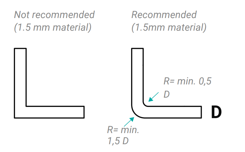
When designing plastic parts, it is essential to incorporate the largest possible radii to facilitate material stretching. Thermoformed parts should always have a minimum radius of 1.5 mm. On the tooling side, a minimum radius is required, which, as a rough rule of thumb (since it depends on many factors), should not be smaller than the initial material thickness.
If sharp edges are necessary, ensure that the radius is at least equal to the starting material thickness. If the radius is smaller, forming the part becomes difficult or even impossible, increasing costs due to longer tool machining times.
2. Design Rule: Draft Angles
The angle between the vertical component wall and the demolding direction is called the draft angle. Since draft angles affect the final shape of the thermoformed part, they must be incorporated early in the CAD model.
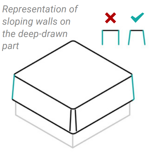
Design vertical walls with draft angles to ensure easy demolding without visible surface defects.
ℹ️ Recommended Draft Angles:
- General recommendation: >2°
- Industry standard for negative molds: 1.5 - 2°
- Industry standard for positive molds: 4 - 6°
3. Design Rule: Forming Ratio and Wall Thickness
The forming ratio describes the relationship between the height and width of the formed area. Since the material is stretched into the mold, it becomes thinner during the process. The forming ratio depends on the tool geometry and final part shape.
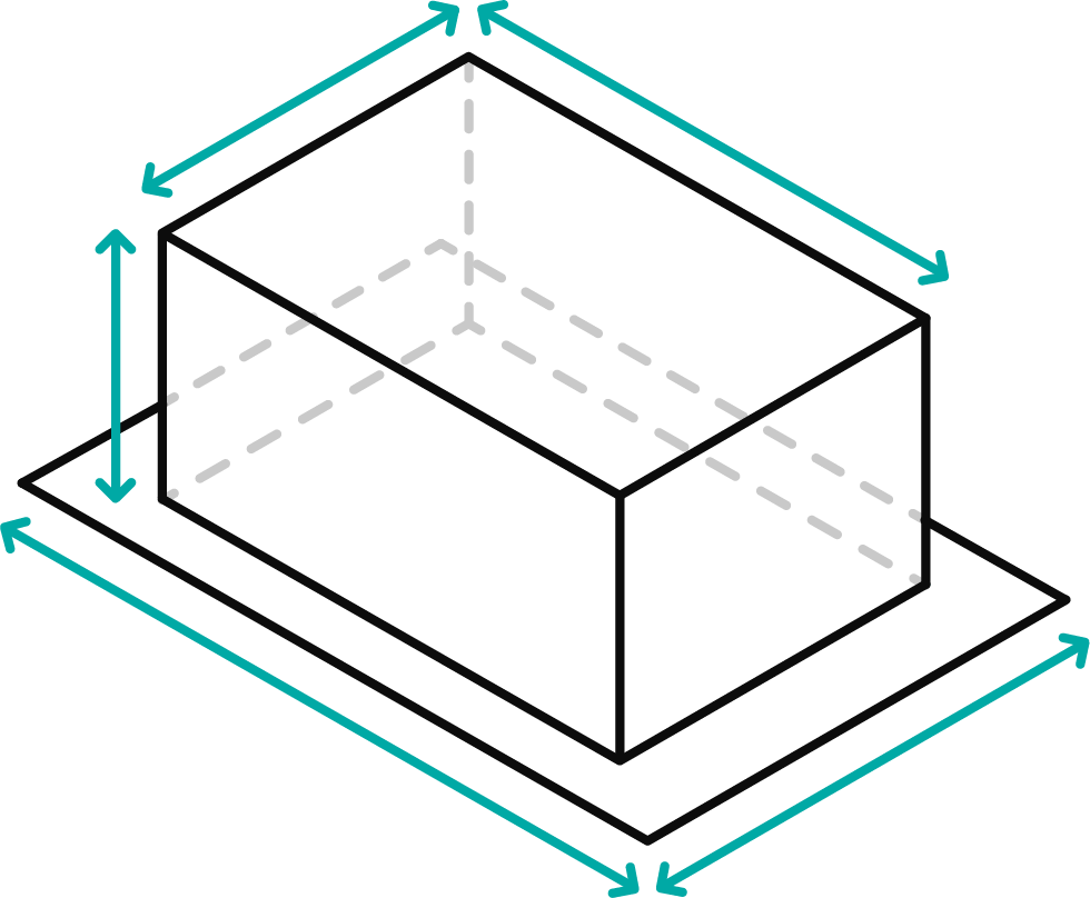
The resulting wall thickness can be roughly calculated using the following formula:
d₂ = (F₁ / F₂) × d₁
Where:
- F₁ = Area of the material blank (excluding clamping edge)
- F₂ = Surface area of the final thermoformed part
- d₁ = Initial material thickness
- d₂ = Final wall thickness
ℹ️ More details on radii, draft angles, and forming ratios can be found in the tolerances section.
4. Design Rule: Positive vs. Negative Forming and Wall Thickness
The deeper the material is stretched during thermoforming, the thinner the remaining wall thickness. Typically, the desired wall thickness is determined first, and then the required starting material thickness is calculated (reverse engineering).
The stretching ratio describes the change in material length from its initial thickness to the final thermoformed part. In general:
- Positive forming results in a lower and more favorable stretch ratio compared to negative forming.
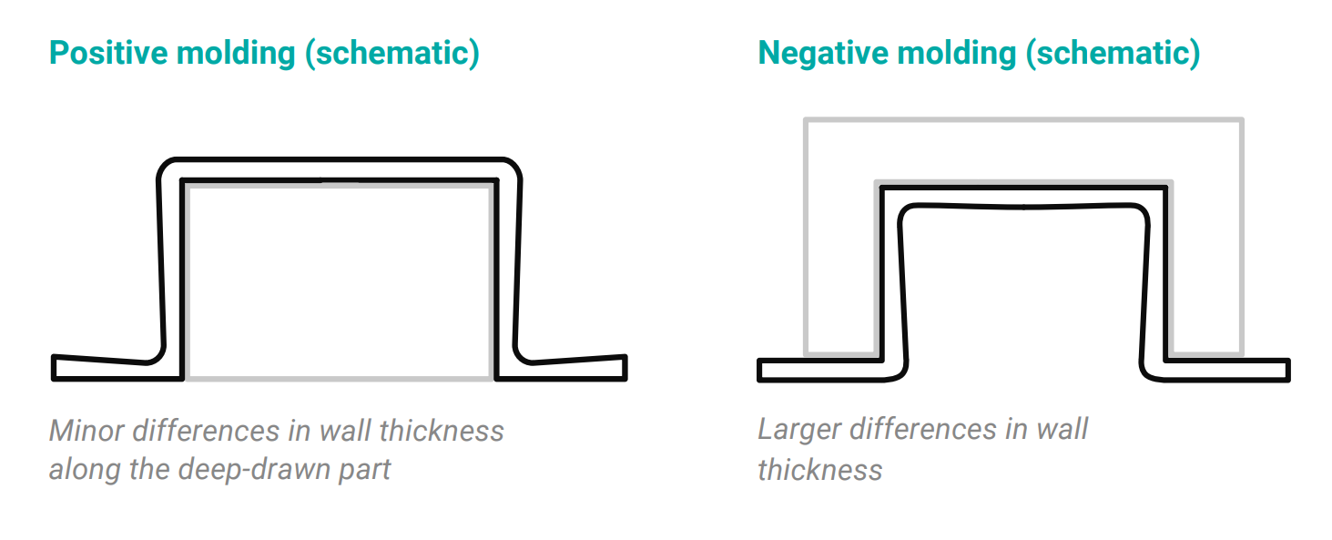
Due to the viscoelastic behavior of thermoplastics during stretching, there are a few rules of thumb to keep in mind during the molding process when designing plastic parts:
- The colder the semi-finished product during stretching, the greater the force required to stretch it.
- The faster the deformation speed, the greater the force required to stretch it.
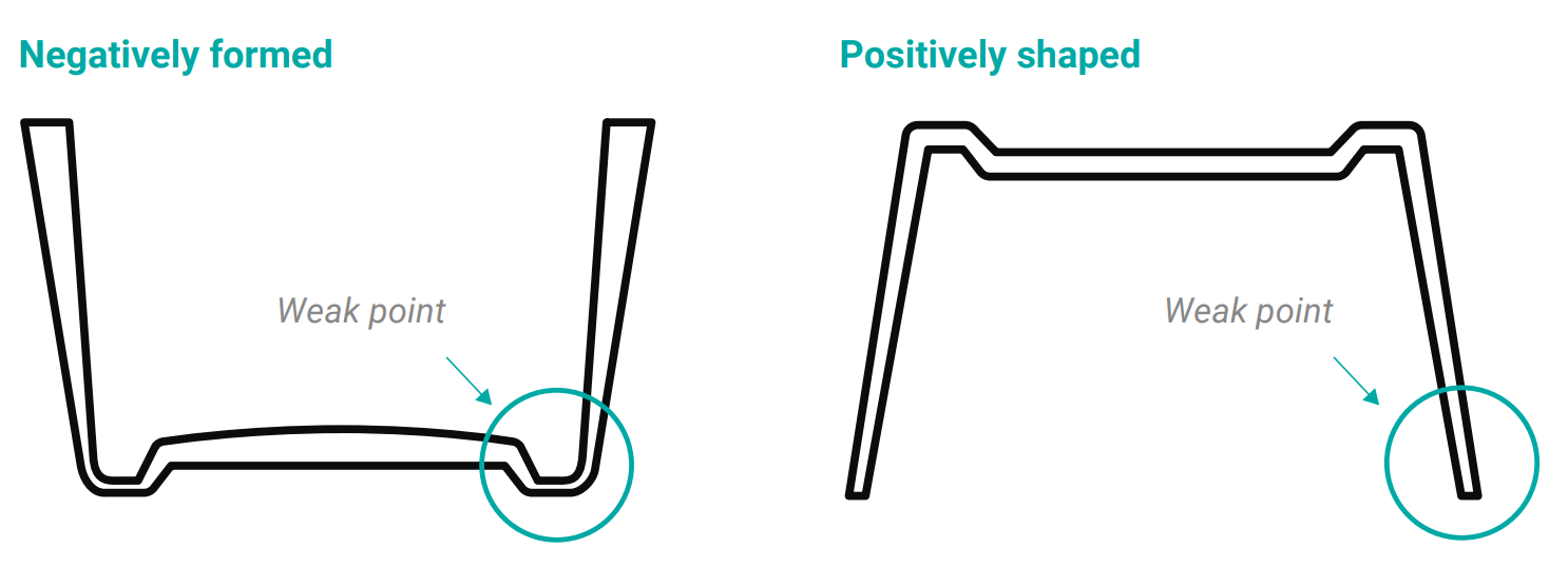
In negatively molded parts, the weak point of the deep-drawn part is therefore in the bottom area after forming, as material is stretched from the edge into the bottom of the mold cavity. This causes the material to thin out. In positively molded parts, the weak point of the deep-drawn part is at the edge, as the material first touches the positive mold at the bottom of the future deep-drawn part and thins out the edge area. Excessively thin initial thicknesses and a poor forming ratio, i.e., the ratio of opening width to opening depth, further exacerbate the negative effect.
5. Design Rule: Material Stretching in Cavities
For negative-formed cavities, the depth-to-width ratio should not exceed 1.5:1. A greater depth results in significant thinning, increasing the risk of rupture at the bottom edges.
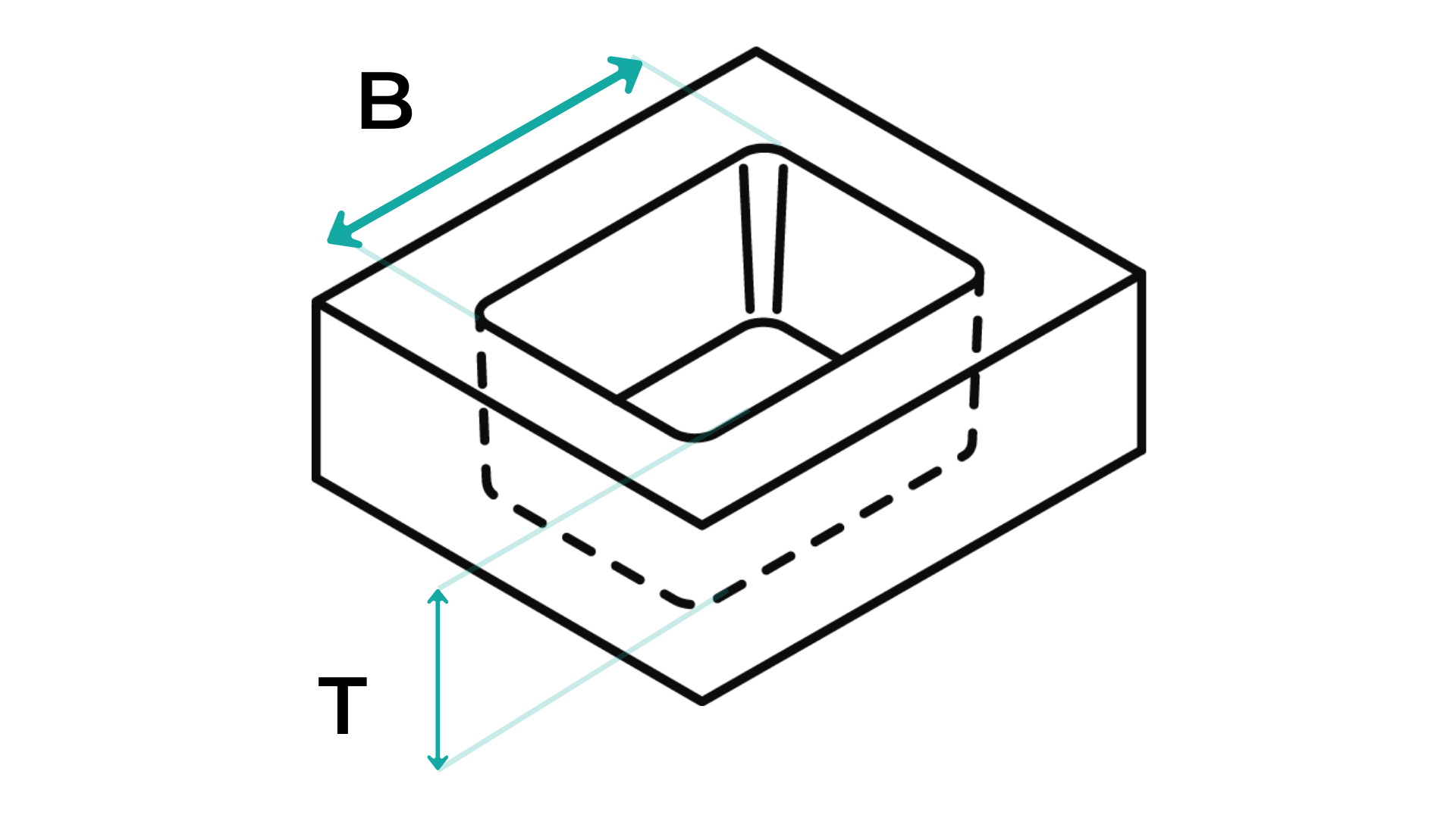
The table explains the possibilities of different pull ratios for negative and positive shapes:
Forming Ratios for Negative and Positive Forms
| Depth-to-Width Ratio | Positive Forming | Negative Forming |
| 0.3:1 | Possible | Possible |
| 0.5:1 | Possible | Needs punch assistance |
| 1:1 | Possible | Needs punch assistance |
| 1.5:1 | Material distortion at the limit | Material distortion at the limit |
| 2:1 | Must be tested; cannot be simulated | Must be tested; cannot be simulated |
6. Design Rule: Transition Contours
As mentioned before, small radii should be avoided in thermoforming. Particularly in precise cavity shapes, slightly rounded contours improve formability while maintaining full functionality.
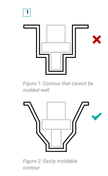
Figure 1 shows a cavity contour that is difficult to deep draw, while Figure 2 shows a modified contour that can be formed easily. Modifying the draft angles and radii makes the deep-drawn part easier to draw, which improves quality. This also minimizes the risk of tearing and guarantees higher reproducibility.
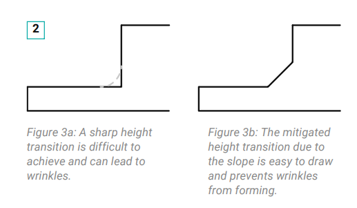
Finally, cycle times are also shorter, which results in a generally more favorable unit price. Transitions from edge contours or stepped areas can also be smoothed out by beveling.
If the radii are too small, there is always a risk of wrinkling during deep drawing, especially with positive molding. To avoid wrinkles, rib-shaped transitions can also be used in plastic design to at least form a wrinkle in a targeted manner during positive deep drawing.
7. Design Rule: Undercuts
Undercut contours represent geometries in the mold that prevent the part from being separated smoothly from the mold. Since, unlike in injection molding, the mold in thermoforming does not consist of two halves, undercuts are generally more difficult to demold. As undercut geometries complicate demolding, they should be avoided as far as possible during design.
This is easier said than done: undercuts play a key role in many deep-drawn parts, as they are used in the form of stacking elements and clamps. Therefore, undercut contours are often unavoidable. For this reason, when designing plastic parts, it is important to reduce them to a level that can be deep-drawn.
8. Design Rule: Shrinkage During Processing
Remember that the processing shrinkage of a plastic thermoformed part is an important factor that influences the final size and shape. After demolding, the part shrinks further due to the material behavior. This shrinkage varies depending on the material and can continue for up to 24 hours after the part has cooled down. In the case of semi-crystalline thermoplastics in particular, post-shrinkage never stops and the part can continue to shrink over time.
To take this into account, the design of the deep-drawing tool should calculate and plan for shrinkage in advance and design the size and geometries of the tool accordingly.
Important factors that influence shrinkage are the selected plastic and the demolding temperature, which can be controlled by the processor. However, keep in mind that the extrusion of the material also plays a role and internal stresses in the semi-finished product must be taken into account when designing plastic parts. A sample test should therefore be carried out before production begins in order to identify potential problems such as shrinkage at an early stage.
9. Design Rule: Thermoformable Tolerances
Deep-drawn parts are designed for most industrial and packaging applications with a tolerance of +/- ~1 mm. This corresponds to the tolerance range according to ISO 2768-c for the 120 to 400 mm length dimensions commonly used in this product area.
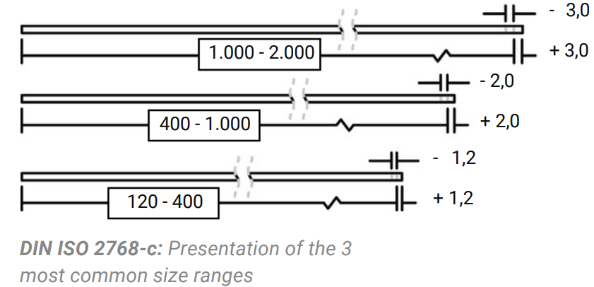
Forming tighter tolerances usually involves additional costs. These are due to longer demolding times, greater manufacturing costs, and/or longer cycle times.
10. Design Rule: Fastening Points in Assemblies
Fixing points are required to assemble various deep-drawn parts or assemblies. Many fastening technology options are used to securely close deep-drawn parts. These must be carefully considered from the outset to ensure that the design is suitable for plastics. Depending on the mechanical load, the frequency of opening and closing, and the stability of the connection, various options are available for achieving a force-fit connection.
In permanently force-fit connections, screws or rivets are often attached to the deep-drawn parts at the transition points between two parts in order to achieve a connection.

11. Design Rule: Stacking Design
If your deep-drawn part is to be stacked, this must be taken into account at an early stage of the design process so that space is left for stacking. Various factors determine the selection of the appropriate stacking technique:
Initial material thickness
The choice of stacking for a thermoformed part depends primarily on the rigidity of the thermoformed part and the sliding properties of the material. The thicker the material (often the case with reusable trays), the better it can be stacked. The poorer the sliding properties of the material, the better the static friction and the better it can be stacked.
Sensitivity of the products
If the components cannot (or should not) be stacked on top of each other, but a few millimeters of air must be maintained, a higher-quality stacking technique is required. The reason for this is that the stacking of the deep-drawn part is self-supporting, i.e., the weight of the trays and their contents must be supported on the tray surface without additional supports.
Urgency of the schedule
Complex stacking techniques with movable stacking elements require production using a flap tool. The manufacture of such a tool is more time-consuming than a relatively simple undercut stacking tool.
12. Design rule for thermoformed plastic parts: Material selection
Softer plastics exhibit greater deformation and higher processing shrinkage after demolding. Materials with high hardness and rigidity are automatically in a better tolerance group in terms of accuracy.
13. Additional tip: Optimally positioned engravings
If you require markings on the thermoformed part, these can be engraved directly into the mold. The cost of engraving can vary greatly depending on how it is applied. As a rule of thumb, negative (recessed) engraving is relatively inexpensive, while positive (raised) engraving is significantly more complex and therefore more expensive.
Designing plastic parts – it's easy with our design tips
By observing these basic design rules, potential sources of error in the end product can be identified and proactively avoided as early as the CAD data creation stage. This allows you to move straight from your product to prototyping.
Do you have any further questions? Then get in touch with us or download our design guide for more information on plastic thermoforming.