Starting Thickness vs. Wall Thickness in Thermoforming: Why Material Thickness Does Not Equal Wall Thickness
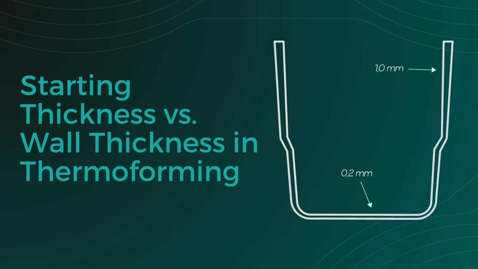
During plastic thermoforming, a plastic sheet or film is heated, stretched and drawn over or into a mold. This changes the material’s original starting thickness: the wall thickness of the finished thermoformed part is not uniform throughout. Anyone designing or sourcing thermoformed plastic parts must understand this relationship in order to dimension parts correctly, avoid thin spots and calculate costs realistically.
Sarah Guaglianone
Updated on August 7, 2026
Share
Starting Thickness and Wall Thickness in Thermoforming – Key Facts at a Glance
The starting thickness is the thickness of the material before thermoforming.
The wall thickness is the thickness of the material in the finished thermoformed part.
During thermoforming, the material is stretched. As a result, the wall thickness is usually lower than the starting thickness.
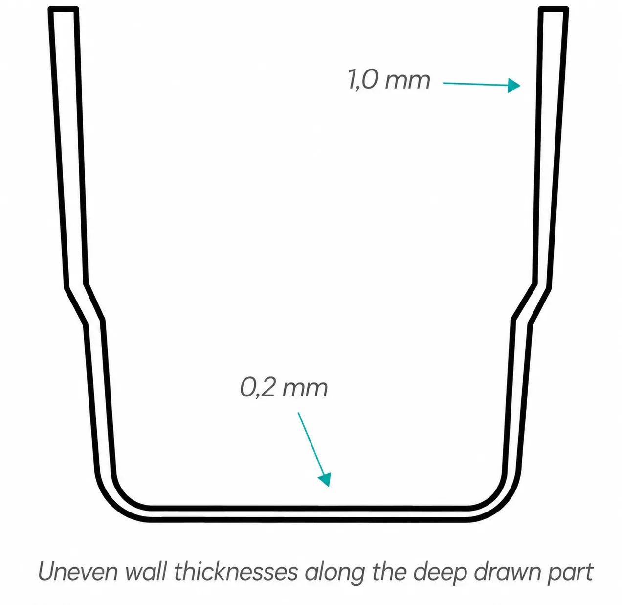
Wall thickness is not constant. Depending on the geometry, depth, forming direction and process conditions, thinner and thicker areas are created.
The resulting wall thickness can be estimated using the formula d2 = (F1 / F2) × d1.
Local variations are possible in practice. Minimum wall thicknesses and safety allowances should therefore be taken into account.
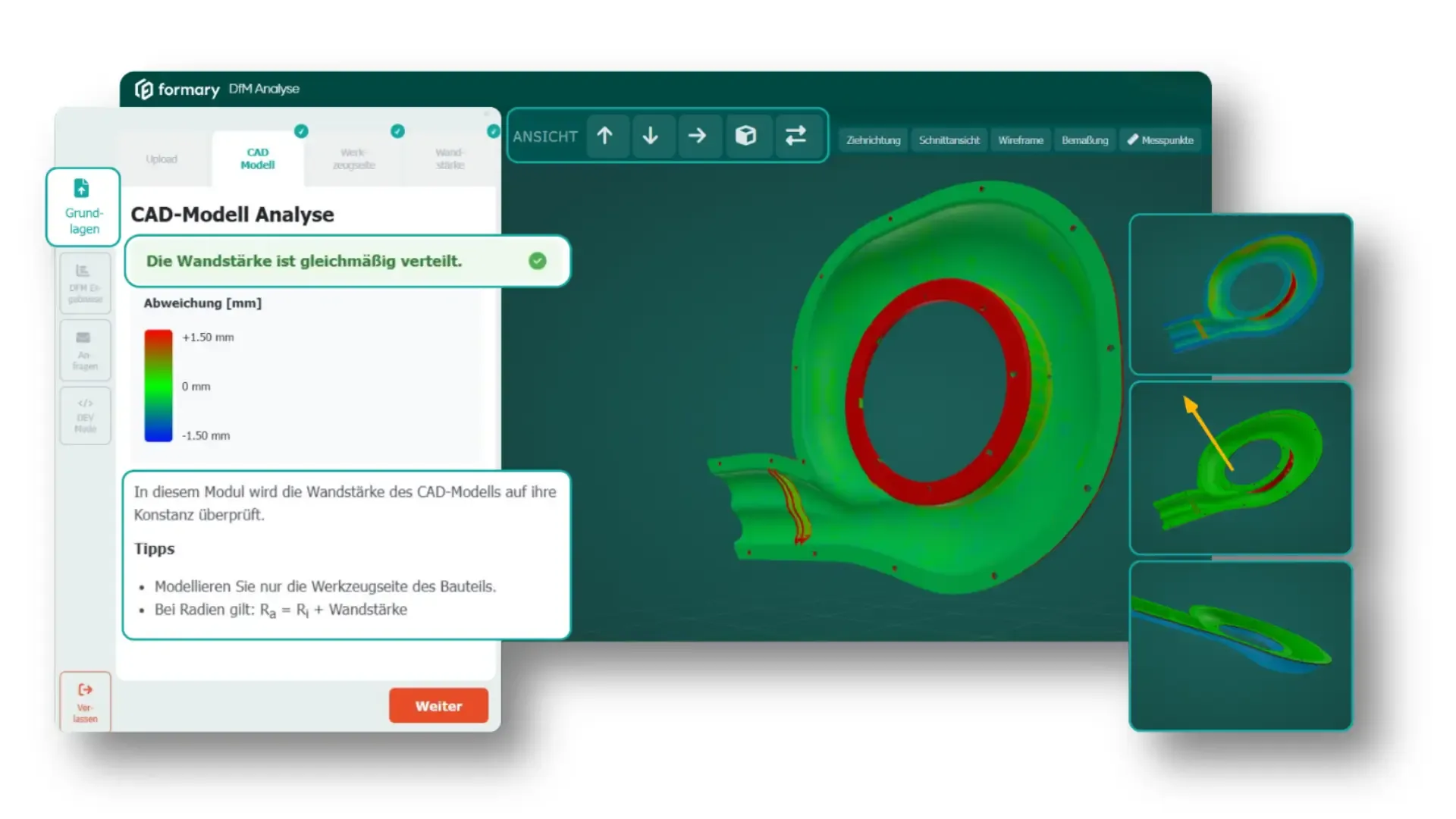
→ Not sure whether your wall thicknesses are suitable for thermoforming? formary’s DfM analysis checks your CAD model for critical wall thicknesses, radii, draft angles and stretch ratios.
What Is the Difference Between Starting Thickness and Wall Thickness?
The starting thickness describes the thickness of the plastic sheet or film before the thermoforming process. At this stage, the thickness is uniform. Wall thickness in plastic thermoforming, by contrast, describes the thickness of the material in the finished thermoformed part. It is created during the forming process and depends on how much the material is stretched in each individual area.
In other words, the starting thickness is the initial value. The wall thickness is the result of the forming process.
Thermoforming vs. Injection Molding: Why Wall Thickness Is Created Differently
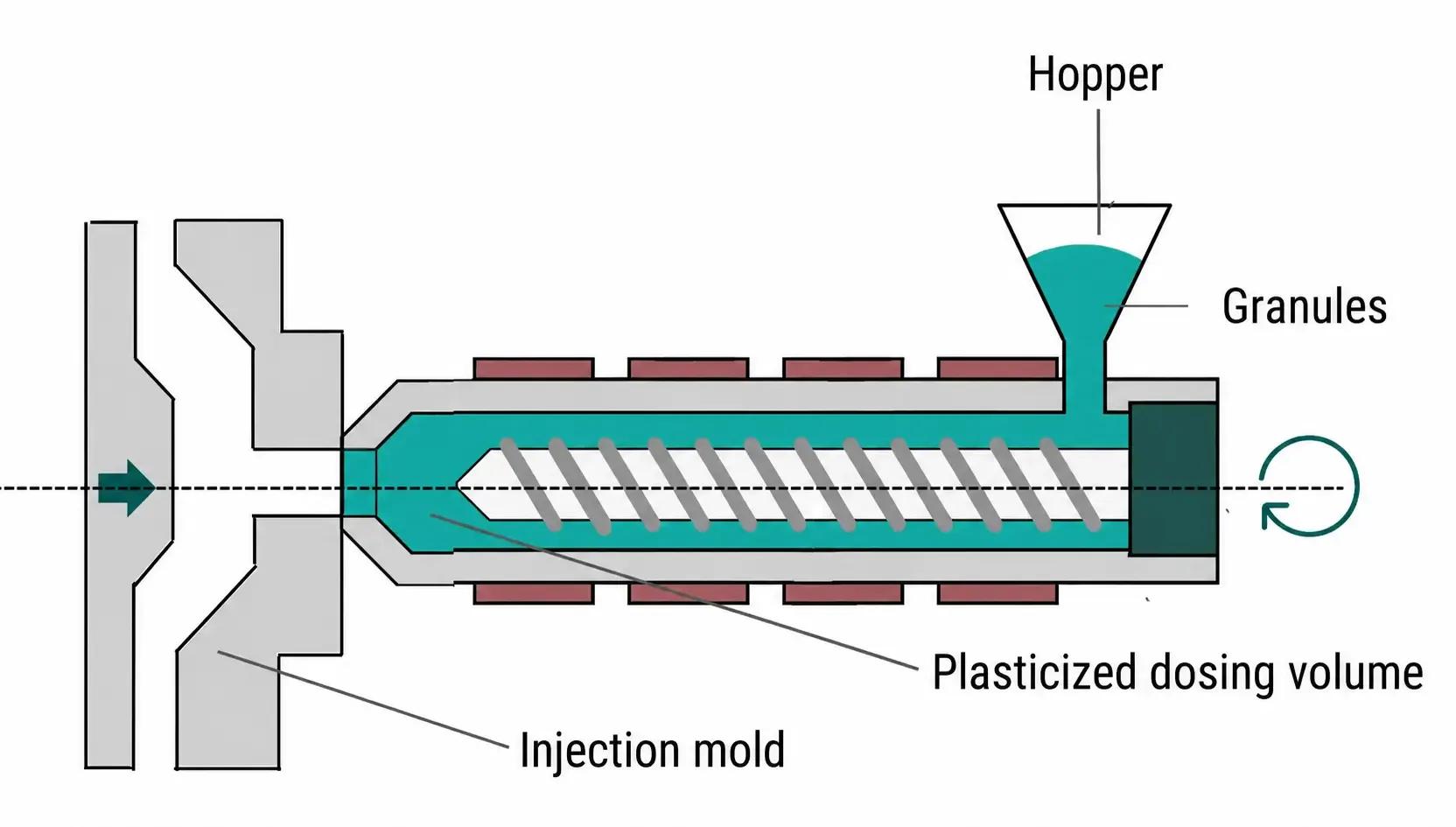
In injection molding, wall thickness is a direct design parameter. The material is injected into a closed, two-sided mold. The cavity therefore defines very precisely what wall thickness is produced in each area.
Thermoforming works differently. Here, a sheet with a defined starting thickness is heated and formed. The final wall thickness is not created by a completely closed mold cavity, but by the stretching of the material during the forming process.
Depending on the part geometry, material, temperature, forming speed, mold design and forming direction, the resulting wall thickness can therefore vary considerably. Thermoformed parts should consequently not be designed around exact wall thicknesses, but around functional minimum wall thicknesses with appropriate tolerances.
Why Does Wall Thickness Decrease During Thermoforming?
The physical principle is simple: material cannot appear from nowhere. When a sheet or film is drawn into depth, the available material must be distributed over a larger surface area. This reduces the wall thickness.
In shallow areas, the wall thickness often remains closer to the starting thickness. In deep areas, tight radii or heavily drawn sections, the material is stretched more and therefore becomes thinner.
💡Important for part design: Areas subject to critical loads should ideally not be located where the material experiences the greatest process-related thinning. If loads cannot be avoided in these areas, a correspondingly greater starting thickness must be selected.
Where Do Thin Spots Occur During Thermoforming?
Thin spots occur where the material is stretched particularly strongly. Their location depends heavily on whether the thermoformed part is produced using male or female forming.
Thin Spots in Female-Formed Parts
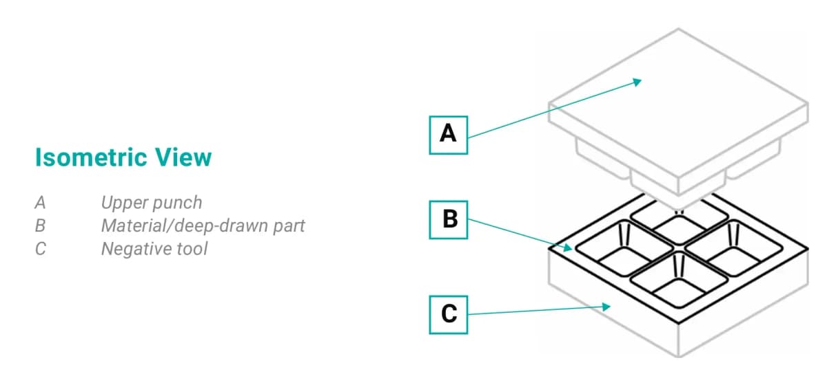
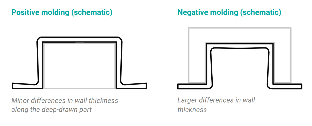
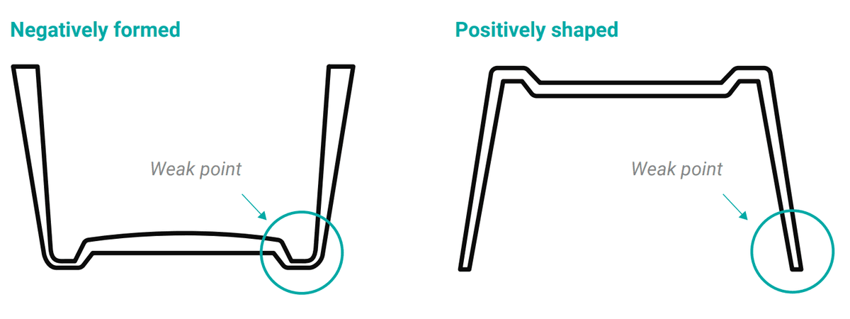
In female forming, the material is drawn into a mold cavity. Material is stretched from the edge toward the bottom of the cavity. The weakest area is therefore often located at the bottom or in the transitions between the bottom and the side wall.
The deeper the cavity and the less favorable the forming ratio, the more strongly the material thins in these areas.
Thin Spots in Male-Formed Parts
In male forming, the material is drawn over a raised mold core. The material first contacts the male mold in what will later become the bottom area. The edge area is then drawn farther downward and is therefore thinned more strongly.
In male-formed parts, the weakest area is consequently often located closer to the edge or along the side walls.
Why the Forming Direction Is Crucial
The decision to use male or female forming should not be based solely on visual or dimensional considerations. The desired wall thickness distribution also plays an important role.
If certain areas of the part are subject to mechanical loads or must maintain a minimum wall thickness, the choice of forming direction can be decisive. Depending on the wall thickness requirements in specific areas, it must therefore be assessed whether male or female forming is more suitable.
💡More design expertise: The formary Design Guide contains further design rules for thermoformed plastic parts, including guidance on radii, draft angles, tolerances and design for thermoforming.
Forming Ratio, Draw Ratio and Area Ratio Explained Simply
In thermoforming, different parameters describe how strongly the material is formed. The forming ratio, draw ratio and area ratio are particularly relevant to the resulting wall thickness.
Forming Ratio
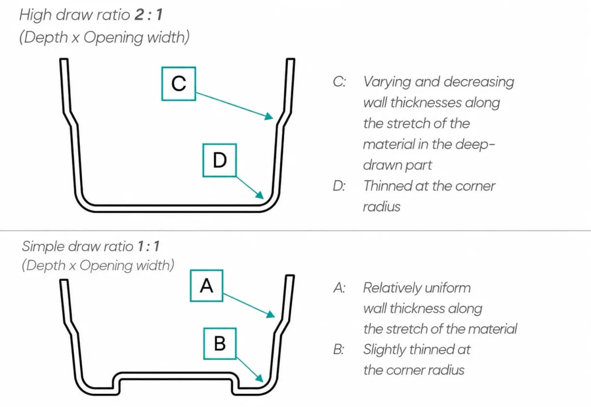
The forming ratio describes the relationship between the height and width of the area to be formed. It therefore indicates how far a limited area of material must be drawn into depth. The greater the depth in relation to the opening width, the more the material has to stretch. This reduces the resulting wall thickness.
The following are particularly critical:
deep, narrow geometries
steep side walls
tight radii
large differences in depth within a part
starting thicknesses that are too low
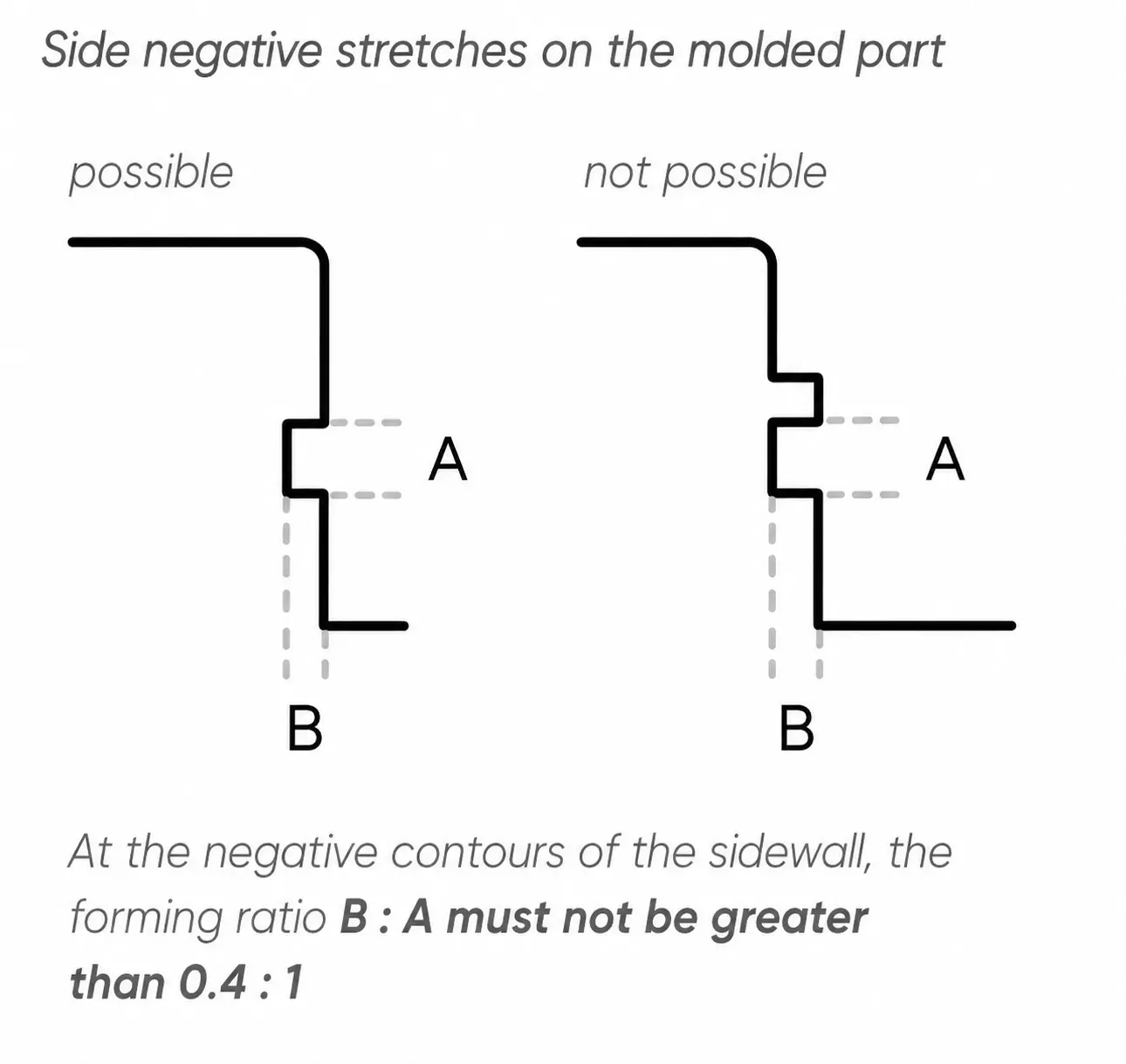
💡Design rule: For female-formed contours on side walls, the ratio between depth and opening width should not become too large. As a guideline, the forming ratio B : A should not exceed approximately 0.4 : 1. If this ratio is exceeded, the risk of thin spots, tears and uneven wall thicknesses increases significantly.
Draw Ratio
The draw ratio describes how strongly the material is stretched during the forming process. A high draw ratio means that the material is drawn deeply and is therefore stretched more strongly.
Area Ratio
The area ratio describes the relationship between the area of the material blank and the surface area of the finished thermoformed part. The larger the surface area of the finished part compared with the original material area, the more strongly the material is stretched.
How Do You Calculate Wall Thickness in Thermoforming?
The resulting wall thickness can be estimated using the following formula:
d2 = (F1 / F2) × d1
Where:
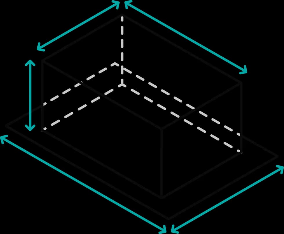
F1: area of the material blank excluding the clamping edge, i.e. length × width
F2: surface area of the thermoformed part after forming
d1: starting thickness of the sheet material
d2: estimated resulting wall thickness
Example: If the surface area of the finished thermoformed part is approximately three times the usable original area, the material is distributed over three times the area. With a starting thickness of 3 mm, this results in a calculated average wall thickness of approximately 1 mm.
Important: This formula only provides an approximate value. The actual wall thickness is not uniform throughout the part. The wall area may exhibit variations between the thinnest and thickest points compared with the estimated d2 value. The design should therefore not target an exactly constant wall thickness, but a reliable minimum wall thickness in the most critical area.
💡More information on digital assessment: The free DfM Check for Thermoformed Plastic Parts guide explains how formary’s digital Design for Manufacturing check identifies critical wall thicknesses, draft angles and geometry issues at an early stage.
Why Can Wall Thickness Not Be Predicted with 100% Accuracy?
Even when calculations, empirical values and pre-stretching are used, a degree of uncertainty remains. Thermoplastics behave viscoelastically. This means that deformation depends on temperature, time, speed and the material’s behavior.
The resulting wall thickness is influenced by factors including:
Material tolerances: The starting thickness of sheets or films is subject to manufacturing tolerances.
Temperature distribution: Different areas of the heated material may have slightly different temperatures.
Heating time: Heating times that are too short can cause uneven forming.
Forming speed: A high forming speed can cause greater local stretching.
Forming direction: Male and female forming produce thin spots in different areas.
Mold temperature: Cold areas of the mold cool the material more quickly and influence material distribution.
Material type: Not every thermoplastic can be stretched to the same extent or with the same uniformity.
💡 Material selection should therefore never be considered in isolation. The decisive factor is always the combination of material, geometry, function and required minimum wall thickness. The Material Guide for Thermoformed Plastic Parts provides an overview of thermoformable thermoplastics, relevant material properties and selection criteria for different applications.
As a general rule: The colder the sheet material is during stretching, the greater the force required for forming. The faster the forming speed, the greater the required force as well. If the material is stretched too strongly or too unevenly, thin spots, tears or structurally unstable areas may occur.
How Can Differences in Wall Thickness Be Reduced?
A completely uniform wall thickness is not realistic in plastic thermoforming. However, designers can positively influence the wall thickness distribution.
Important measures include:
Use generous radii: Tight radii concentrate stretching and increase the risk of thin spots.
Avoid extreme draw ratios: Deep, narrow areas are particularly critical.
Prefer uniform depths: Large differences in depth make uniform material distribution more difficult.
Include draft angles: Draft angles of approximately 2–5° make demolding easier and reduce stress.
Choose the forming direction deliberately: Male and female forming result in different wall thickness distributions.
Do not select the starting thickness too tightly: A starting thickness that is too low increases the risk of critical thin spots.
Test prototypes: Samples reveal the actual wall thickness distribution and allow adjustments before series production.
💡 Many of these points are among the fundamental design rules for thermoformed parts. A detailed overview is available in the article Design Rules for Thermoformed Plastic Parts.
Pre-Stretching with a Plug Assist: Influencing Wall Thickness Distribution
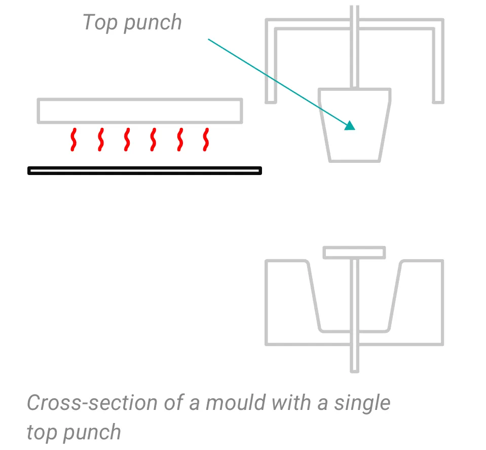
For demanding geometries, a plug assist can help improve material distribution. During pre-stretching, an additional plug preforms the heated material before it is drawn completely over the mold or into the cavity.
The objective: The material is distributed more selectively. This can prevent excessive material from remaining in non-critical areas while critical areas become too thin.
A plug assist is particularly useful for:
deep cavities
high draw ratios
female molds
demanding geometries
parts with defined minimum wall thicknesses
Nevertheless: Pre-stretching does not replace a design suitable for thermoforming. If the draw ratio is too high for the material, starting thickness and geometry, thin spots or tears may still occur even when a plug assist is used.
What Starting Thickness Is Appropriate?
An appropriate starting thickness depends on more than the desired wall thickness. The main factors are the part’s function, handling, application, material type, geometry and cost sensitivity.
Important design questions include:
Does the thermoformed part need to protect, support, guide, cover or merely position something?
Will the part be moved manually, gripped automatically, stacked or transported?
Are there mechanical, thermal, chemical or hygiene requirements?
Are there critical functional surfaces that require a minimum wall thickness?
How deep is the part?
What radii, side walls and contours are planned?
Which material is to be used?
💡Practical tip: Use formary’s DfM analysis to assess CAD models for critical wall thickness areas before the mold is manufactured. The software shows where the material becomes too thin and provides recommendations for design modifications. This helps you avoid costly rework and ensure that minimum wall thicknesses are maintained.
Common Mistake: Selecting a Starting Thickness That Is Too Low
A common mistake in practice is calculating the starting thickness too tightly in order to save material costs. As a result, critical areas become too thin and the part either fails mechanically or cannot withstand the required loads.
Consequences:
cracks or holes during the thermoforming process
parts breaking during handling or use
rework or mold modifications being required
project delays and higher overall costs
A better approach is to select the starting thickness with a safety allowance, manufacture prototypes and measure the actual wall thicknesses. The additional cost of using slightly thicker starting material is often lower than the cost of scrap, mold modifications or failed production runs.
Conclusion: Starting Thickness Is the Initial Value, Wall Thickness Is the Result
The starting thickness of the material is not the same as the wall thickness of the finished thermoformed part. During plastic thermoforming, the material is stretched. This reduces the wall thickness, which varies depending on the geometry, forming direction, material and process conditions.
The forming ratio, draw ratio and area ratio help estimate the subsequent wall thickness more accurately. The formula d2 = (F1 / F2) × d1 provides an approximate value. In practice, however, local variations must be expected.
Anyone designing thermoformed parts should therefore define minimum wall thicknesses, include safety allowances and have feasibility assessed before mold production.
formary supports you with DfM analysis, material consulting and transparent cost calculations. Use the configurator to configure your project and receive a quotation within 24 hours.
The starting thickness is the thickness of the plastic sheet or film before thermoforming. The wall thickness is the thickness of the material in the finished thermoformed part. During thermoforming, the material is stretched, causing the wall thickness in different areas to become thinner than the starting thickness. The deeper an area is drawn, the thinner the wall becomes in that area.
The material is stretched to different degrees during thermoforming. In shallow areas, the wall thickness remains close to the starting thickness, while in deep areas the material is stretched more strongly and becomes thinner. This wall thickness distribution is physically unavoidable because the available material is distributed over a larger surface area.
Wall thickness can be estimated using the formula d2 = (F1 / F2) × d1. F1 is the area of the material blank excluding the clamping edge, F2 is the surface area of the finished thermoformed part, d1 is the starting thickness and d2 is the resulting wall thickness.
The wall area may exhibit variations between the thinnest and thickest points compared with the estimated d2 value. Minimum wall thicknesses and safety allowances should therefore be used.
The forming ratio describes the relationship between the height and width of the area to be formed. The greater the depth in relation to the opening width, the more strongly the material is stretched and the thinner the wall thickness may become.
In female-formed parts, thin spots often occur in the bottom area. In male-formed parts, the critical area is often closer to the edge or along the side walls. The precise location depends on the geometry, material and process conditions.
Differences in wall thickness can be reduced through generous radii, appropriate draw ratios, uniform depths, a suitable forming direction and sufficient starting thickness. For demanding geometries, a plug assist can help improve material distribution.
That depends on the geometry, depth, material, loads and forming ratio. The decisive factor is not only the starting thickness, but the minimum wall thickness remaining in the most critical area after stretching.
For a technical assessment, CAD data, quantities, the preferred material or material requirements, operating conditions, temperature requirements, visual requirements and critical functional surfaces are helpful.
Further Content
Thermoformed Parts in Practice
Supplier Guide for Plastic Thermoformed Parts – 10 Key Factors That Matter
Choosing the right supplier for plastic thermoformed parts is crucial for the quality, efficiency, and cost-effectiveness of your production. Our 10 tips will show you what to look for when selecting a supplier.
Platform & Features
3 Factors That Accelerate Your Procurement with formary
The three key factors—time, speed, and efficiency—are crucial for success in industrial manufacturing, from inquiry to delivery. That’s why formary has optimized this process, significantly accelerating the procurement of plastic thermoformed parts. Learn more in this article.
Thermoformed Parts in Practice
Rapid Prototyping in Thermoforming – Definition, Benefits & Processes
Rapid prototyping is used in product development to quickly create preliminary models. In thermoforming, rapid prototyping offers numerous advantages for producing high-quality prototypes efficiently and cost-effectively.
Platform & Features
Project Planning in Thermoforming – From Concept to Mass Production
From the initial idea to mass production, various factors must be considered in thermoforming project planning, including material selection, tool manufacturing, and quality control. This article provides a detailed look at how a thermoforming project with formary is executed.
Thermoformed Parts in Practice
Thermoforming vs. 3D Printing – Advantages, Disadvantages, Differences, and Similarities
Plastic parts are manufactured using various processing methods. In this article, we focus on comparing the processes of plastic thermoforming and 3D printing.
Thermoformed Parts in Practice
Injection Molding vs. Plastic Thermoforming – Advantages, Disadvantages, Differences, and Similarities
In the world of plastic processing, there are various common manufacturing methods used to produce precise plastic components for industrial applications. We compare two of them: Injection Molding and Plastic Thermoforming.
Thermoformed Parts in Practice
Checking CAD Models for Thermoformability: The Designer's Guide
Whether a plastic part is thermoformable is determined in the CAD model. Anyone who discusses geometry, wall thicknesses, and demoldability only after the first sampling pays for this loop with tool modifications, material waste, and lost weeks in the project timeline. This can be avoided during design: with a structured check that evaluates each model along this guide and makes typical sources of error visible early on.
Thermoformed Parts in Practice
Design for Manufacturing (DfM): Guide to Manufacturing-Oriented Design
With the new Design for Manufacturing analysis from formary, it is now possible to check CAD data for thermoformability in a matter of seconds, allowing potential sources of error to be identified early on before they become costly. Read on to find out what features the DfM software offers and what the Design for Manufacturing principle entails.
Thermoformed Parts in Practice
Unit Costs and Tooling Costs in Thermoforming: Cost Factors and Scalability
The costs in plastic thermoforming are a crucial factor for the economic efficiency and planning of a project. They depend on various influences along the process chain and change depending on production volume and requirements. This article explains how costs in plastic thermoforming are composed, how they develop with increasing quantities and when the process becomes particularly worthwhile.